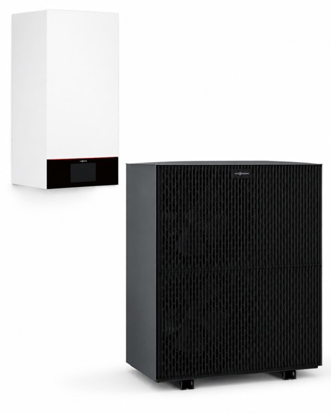
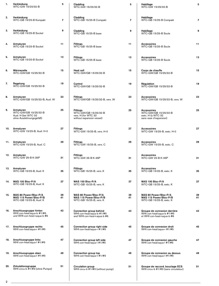
1 Verkleidung – WTC-GW 15/25/32-B Zeichnung 1 2
2 Verkleidung – WTC-GB 15/25-B Kompakt
3 Verkleidung – WTC-GB 15/25-B Sockel
4 Armaturen – WTC-GB 15/25-B Sockel
5 Armaturen – WTC-GB 15/25-B Sockel
6 Wärmezelle – WTC-GW/GB 15/25/32-B
7 Regelung – WTC-GW/GB 15/25/32-B
8 Armaturen – WTC-GW/GB 15/25/32-B, Ausf. W
9 Armaturen – WTC-GW/GB 15/25/32-B, Ausf. H
10 Armaturen – WTC-GW 15/25-B, Ausf. H-0
11 Armaturen – WTC-GW 25-B, Ausf. C
12 Armaturen – WTC-GW 25-B K-35P Zeichnung 1 2
13 Armaturen – WTC-GB 15/25-B, Ausf. K
14 WAS 100 Bloc-P/A – WTC-GB 15/25-B, Ausf. K
15 WAS 115 Power/Bloc-P/B – WTC-GB 15/25-B, Ausf. K Zeichnung 1 2
16 Anschlussgruppe hinten – WHI con-heat/aqua-b #1/#5
17 Anschlussgruppe rechts – WHI con-heat/aqua-r #1/#5
18 Anschlussgruppe links – WHI con-heat/aqua-l #1/#5
19 Anschlussgruppe oben – WHI con-heat/aqua-t #1/#5
20 Zirkulationsgruppe – WHI circu-b #1/#3 (ohne Pumpe)
21 Zirkulationsgruppe rechts – WHI circu-r #1/#3 (ohne Pumpe) Zeichnung 1 2
22 Zirkulationsgruppe links – WHI circu-l #1/#3 (ohne Pumpe)
23 Zirkulationsgruppe oben – WHI circu-t #1/#3 (ohne Pumpe)
24 Zirkulationsgruppe hinten – WHI circu-b #1/#2 und WHI circu 15-3-b #3 (mit Pumpe)
25 Zirkulationsgruppe rechts – WHI circu-r #1/#2 (mit Pumpe)
26 Zirkulationsgruppe links – WHI circu 15-3-l #1/#2 (mit Pumpe)
27 Zirkulationsgruppe oben – WHI circu-t #1/#2 (mit Pumpe)
28 Hydraulik – WTC-GB 15/25, Ausf. S
29 Anschlussgruppe
30 Zubehör – WTC-B
31 Zubehör – WTC-B Zeichnung 1 2
32 Aqua-Anschlussgruppen WHA 4.0 und 4.1
33 Aqua-Anschlussgruppen WHA 5.0/5.1 und Sicherheitsarmaturengruppen
34 Aqua-Anschlussgruppen WHA C 4.0 und 4.1, WHA 4.4 und 4.5
35 Pumpen-/Mischergruppen, Verteiler Zeichnung 1 2 3
36 Hydraulische Weichen, Systemtrennung, Doppelweiche Zeichnung 1 2 3
37 3-Wege-Mischer mit Stellknopf, 3-Wege-Umschaltventilset, Neutralisationseinrichtungen, Heizungswasser-Nachfüllstation Zeichnung 1 2
38 Regelungs-Zubehör Zeichnung 1 2 3
39 Service
40 WAL-PP DN 60
41 WAL-PP ab DN 80 Zeichnung 1 2